Utilisateur:Cyprien
FTDI Basic auto-reset for LPC

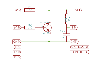
LPC micro-controlers can be programmed using the standard serial line using the ISP mode. This requires to have the ISP pin grounded when the LPC goes out of reset. It's often done using two micro-switches you have to manually press and release in the correct order.

How does it work?
- When the
DTRsignal goes up, theResetis pulled down, putting the LPC into reset. At this moment C1 starts to discharge through R3, and ifDTRis asserted long enough, theISPpin is put low too. - When
DTRis back to normal, the LPC goes out ofReset, and if C1 is discharged enough entersISPmode.
I used 2200 ohm for R3 and 47uF for C1 (which I had close), which gives a RC time of about 100ms. Note that a smaller capacitor can be used, as soon as R3 value is adapted. In my experience a 100ms DTR signal is enough to trigger both Reset and ISP mode, whereas a 10ms signal just triggers Reset. This is perfect!
Cons: if you want to manually push the reset button, disconnect the ISP pin as it will likely be triggered.
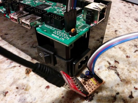
Here's a picture of the circuit soldered on a Vero Board (compact, some holes hold two pins together) and connected to the DTPlug :

